CONTROLE REMOTO 433MHz
433MHz 4Ch Remote Controller
16.019
52
5
Introduction: 433MHz 4Ch Remote Controller
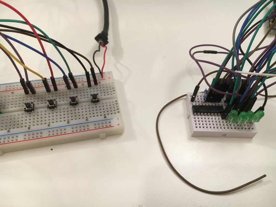
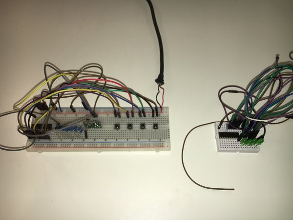
This is a guide on how to make a 4CH 433MHz wireless transmitter and receiver to control just about anything you want, I connected 4 LED's just to demonstrate.
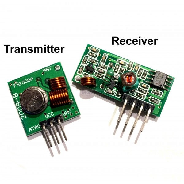
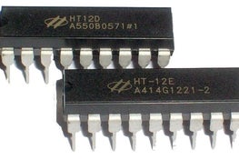
I used the HT12D decoder and the HT12E encoder for this project and a cheap 433MHz RF transmitter and receiver module. The range with an antenna is 25m.
Step 1: Parts
To make this project I used the items below:
- 433MHz RF module TX and RX.
- HT12E.
- HT12D.
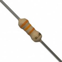
- 750K Ohm resistor.
- 33K Ohm resistor.
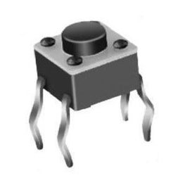
- 4x pushbuttons.
- 4x LEDs.
- Jumper wires (male to male).
You will also need two breadboards and two 5V power supply. I used a USB cable to power up the remote, and a 9V battery with a 5V regulator on my receiver.
I did not use any resistors between the LEDs and the receiver, I just used them to test so I did not need them.
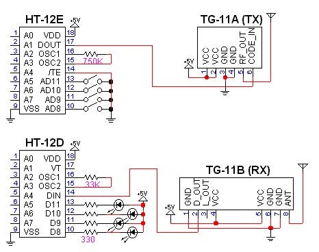
Step 2: Schematic
Follow the schematic when mounting on the breadboard.
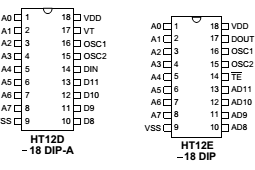
Connect 1,2,3,4,5,6,7,8 and 9 together to ground on the HT12E and HT12D chip.
The receiver and transmitter modules in the schematic are a little different on the pinout than on the once I used.
Step 3: Antenna
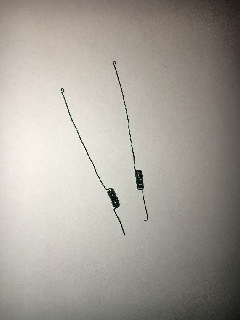
The 433MHz receiver and transmitter that I used are the cheapest once you can find online and they are perfectly fine for short range operations, if you want to increase the range of the transmitter and receiver than I suggest that you add an antenna to the two modules. I used an antenna design that i found and the instructions for the antennas are at Ben's PDF.
with these antennas you can easily get up to 25m outside.
The range will also increase if you supply the transmitter module with 12V (thats the maximum voltage!) but not the receiver, it can only handle 5V.
Step 4: Testing
When you have connected everything than its time to test it, its best to test with LED's first to see if everything works.
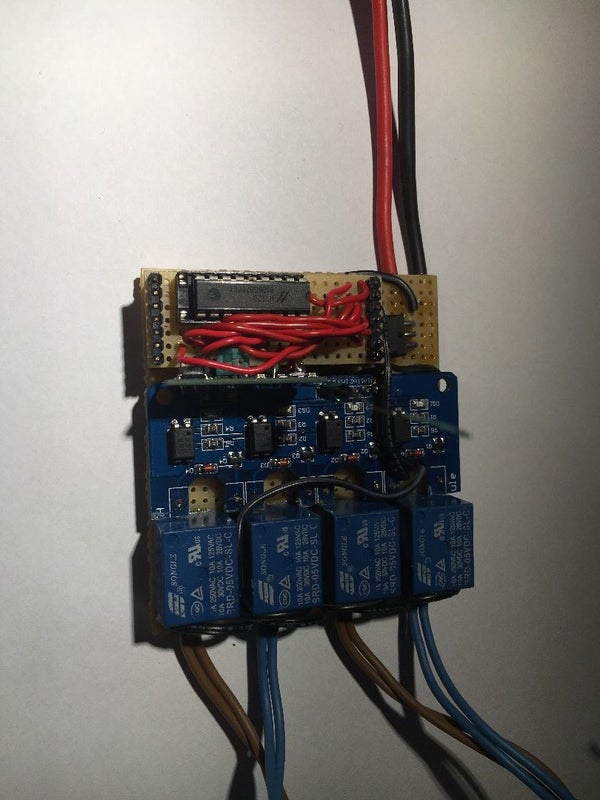
In the picture above you can see that I have soldered the receiver to 4 reléy's, what i have done is that i have made a wireless control for two motors, I'm using this on a RC car that I have built.
THANKS FOR VIEWING
If you like this project than check out my other DIY projects on my channel. If you have any questions or tips for this project than post them in the comments.







We have a be nice policy.
Please be positive and constructive.